
Why springs fail at the surface
When a compression spring is loaded, the material is put into torsion, and the highest shear stress appears on the inner surface of the wire — the side of the coil facing the axis. That is where fatigue cracks almost always start.
The reason is straightforward: crack initiation needs tensile stress. Tension opens the material and grows the micro-crack. However clean the interior of the material is, the smallest surface notch, decarburised layer or handling mark becomes an initiation site under that tension.
Shot peening changes the sign of that equation.
What peening does
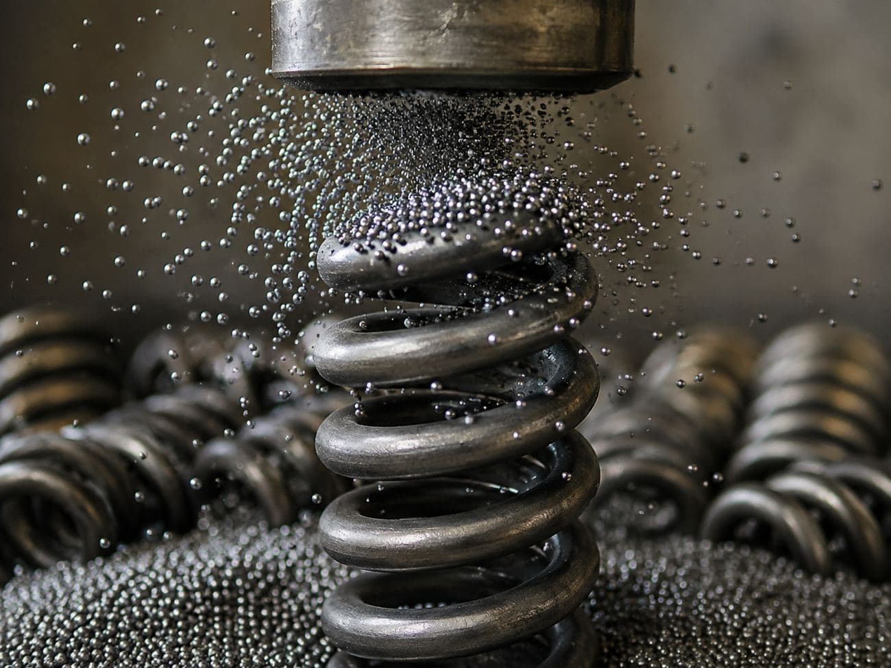
Spherical media striking the surface at high velocity make a thin layer flow plastically — that layer wants to spread. The material immediately beneath it is still elastic and refuses to spread, pulling it back.
The result is a surface layer held permanently in compression. This is compressive residual stress, and it is present even when the spring carries no load at all.
Tensile stress reaching the surface in service must first overcome this compressive residual stress, which means the stress that actually initiates a crack drops substantially — with the geometry, material and load all unchanged.
Three points on that curve matter: the stress at the surface, the depth at which compression peaks, and the crossover depth. The last one tells you how far the protection reaches. In typical spring work it falls between 0.20 and 0.35 mm.
The mild tensile region to the right is unavoidable: forces must balance across the section, so pressing the surface into compression is paid for somewhere deeper. What matters is that the tensile region sits at a depth where the working stress is low.
How much it buys
Published work and field data put the fatigue life improvement at two to five times. Stress-peened suspension springs can go higher. Quoting a single multiplier is misleading, though — the outcome depends on four things:
| Factor | Effect on the gain |
|---|---|
| Material strength | Higher strength brings higher notch sensitivity, so the contribution of peening grows with it. |
| Working stress level | The gain is clearest in highly stressed springs; at low stress the difference narrows. |
| Surface quality | Peening compensates for a poor incoming surface but does not erase it. |
| Peening parameters | Incomplete coverage or over-peening can wipe out most of the benefit. |
Shot peening does not rescue a weak design. Holding up an over-stressed spring with peening is a temporary fix. Peening extends the life of a correctly designed spring; on a badly designed one it only delays the failure.
The three controlled parameters
1 · Almen intensity
Peening strength cannot be measured directly, so it is measured by proxy. A standard steel strip is exposed to the stream; because only one face is treated, the strip curves, and that arc height is measured. Strip type and value are written together — for example 0.40 mmA.
Intensity is fixed by the saturation curve: the point at which doubling the exposure time increases arc height by less than 10%. The procedure is defined in SAE J442 and J443.
2 · Coverage
This is how much of the surface carries impact dimples. In practice 98% is treated as full coverage, and the expected benefit does not appear until complete coverage is reached. An uncovered patch remains an initiation site surrounded by protected material — which can end up worse than not peening at all.
3 · Media type and condition
Cut wire, cast steel shot, ceramic or glass — the choice follows the target intensity and the acceptable surface roughness. The critical point is not the choice but the maintenance: broken media turns angular and cuts the surface instead of pressing it. A cabinet with a failing separator produces the wrong result from the right parameters.
We can set peening parameters together, against your spring geometry.
Talk to our engineersStress peening and dual peening
Stress peening means peening the spring while it is held compressed. Residual stress formed while the material is already strained settles at a higher compressive value once the load is released. It is common in suspension springs and gives a measurable gain over plain peening.
Dual peening runs two stages: high intensity with larger media, then low intensity with finer media. The second stage improves surface roughness without disturbing the deep compressive layer, smoothing the crater edges left by the first.
Four common mistakes
- 1Assuming coverage from time. "We peen for 20 seconds" is not a specification. Coverage varies with part geometry and nozzle position, and has to be verified.
- 2Over-peening. Past a certain point, more intensity or time creates surface laps and micro-tearing. The compressive gain is spent paying for the new notches.
- 3Skipping media control. Where broken media ratio goes unchecked, results degrade quietly while the paperwork stays identical.
- 4Neglecting the inner surface. The highest stress in a spring is on the inside of the coil, and that is the hardest place for media to reach. If nozzle angle does not account for it, the one region that needed protection is the one that did not get it.
Standards
| Standard | Scope |
|---|---|
| SAE J442 | Almen strip and test fixture |
| SAE J443 | Almen strip procedure, saturation curve |
| SAE J441 | Cut wire shot specification |
| SAE J2441 | Shot peening practice |
| EN 13906-1 | Compression spring design and calculation |
- Fatigue cracks start at the surface; peening holds that surface in compression and delays initiation.
- The protective layer typically reaches 0.2–0.35 mm; a balancing tensile region deeper in the section is unavoidable.
- Reported life gains run from two to five times, but depend on material, stress level and parameters.
- Three parameters are controlled: Almen intensity, coverage and media condition. Lose one and the gain goes.
- Stress peening adds further benefit in suspension springs; dual peening improves surface roughness.
Editorial note — This article is general information. Formulas, standards and values given here describe established engineering practice and are not a design specification. Any final spring design must be verified against the load case, operating conditions and applicable standards of the individual application. Tenvor Springs accepts no liability for designs derived from this text without such verification.